|
Home
History
Environmental Threat
Site Characterization
Man. Gas Processes
Plant Wastes
Contamination Threat Modes
Residuals - Components
Sources of MGP Liquid Effluent
FMG Plants in the US
Parallel MG Technologies
Think you've found a gas works?
Locating and Confirming a Site
Locations of US Gas Plants
FMGP In The News
FMGP In The Arts
Coal-tar Site Litigation
Related sites on the Internet
Literature of Manufactured Gas
Hatheway Harangues
Publications by Dr. Hatheway
Slide Shows by Dr. Hatheway
Slide Shows by others
Hatheway Bio
Hatheway Resume
Legal Considerations
|
|

Gas Manufacturing Processes
It is well proven that artificial gas can be manufactured from literally any organic matter. Coal has been the favorite feedstock because of its abundance in those portions of the temperate climates where the industrial revolution was able to take place, largely due to steam energy produced from the burning of coal. The main historic processes of gas manufacture are discussed in this section of the website.
To Page #2 - TREATMENT COMPONENTS of the GAS PLANT
|
|
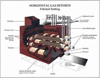
Coal-Gas Retort Bench
Coal-gas Retorts were made in the general configuration shown, and, after about 1880 generally came as a solid ceramic tube of a Dee cross-section as a measure to avoid stress-prevalent sharp corners. Retorts experienced thermal damage from the typical four-to-six hour charge cycles and commonly needed replacement within months to two years. Most plant sites will be found somewhat littered with broken retort fragments and bricks stripped from aged Bench housings, the which provided the heat-conserving support structure and the by-pass flues to heat the retorts in the absence of oxygen. Riser Pipes are here labeled Gas Off take Pipes. This is a Bench of Eights, more common to the United Kingdom, and sharing a single Furnace. Furnaces were fed by coal, by coke raked from the retorts on completion of each gas run, and sometimes supplemented by flowing tar recovered at various points in the Clarification Process. It is best not to assume that plant tar residuals were consumed in any degree unless backed by reliable plant or company records (Artwork by Robin Snyder, Gas Works Illustrator; ) (click on the image for a larger version of this image).
|
BROWN'S DIRECTORY of AMERICAN GAS COMPANIES
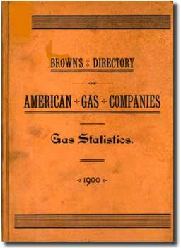 |
| Brown's Directory began publication in 1887 as a yearly compendium of organizational and process- oriented information solicited by the publisher, on a voluntary basis, from the nation's manufactured gas companies. Being of a voluntary basis, the Directory was always at the mercy of the correspondents as to the accuracy, completeness and timeliness of submissions. The Directory has changed ownership several times, mainly later in its ongoing history, and is published yet today. Five years are missing from the series (never published) in the 1890s and the content and organization of the Directory varies considerably by the year. A major shortcoming of the Directory is that gas companies with multiple gasworks in the same city are indistinguishable as to the number and location of individual plants and of the individual yearly production for multiple gasworks under the same ownership. One of the techniques of assessing the toxicity threat of gas plant sites is to compute the total volumes of expected gas-manufacturing residuals and wastes, as a function of the yearly production of gas at each gasworks. Fortunately, the production figures for single-plant companies generally are to be found in these directories. |
|
|
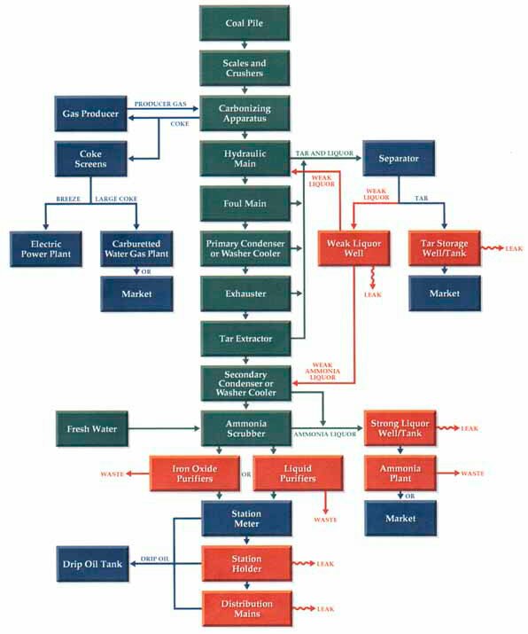
Carburetted Water Gas Plant (Post-1900)
This outstanding method of gas-manufacturing was invented by T.S.C. Lowe, one of America's truly outstanding engineering geniuses. This process diagram begins on the left, with the three cylindrical Generator units of the system, developed and patented in 1875, to utilize coke as a reactor bed in the Generator, with steam injected, from the Boiler, into the Generator, then passed to the Carburetor for injection of light petroleum oils (for gas light illumination) and then into the Superheater, where more checker-board fire bricks retained heat to flash the composite gas into a fixed nature, followed by a Wash Box seal to pass the raw gas through a Tar Separator, and Scrubber, then into the Relief Holder (serving a pressure-equalization role far different from the Relief Holder of coal-gas plants). From this position the gas went on to experience a Condenser, an Exhauster, another Tar Extractor, and, finally, the purifier boxes, then the Station Meter and a Storage Holder identical for what was required at coal-gas plants. In fact, make use of this illustration for superior details to those shown for the coal-gas plant. A single three-unit Generator Set, of three cylinders, could make much more gas per day than could coal-gas benches, in addition, saving on labor and operating space in the Generator House. One major flaw came into being as coke became scarce after 1910 and, at the same time, motor vehicle fuel sales crowded the usual light gas oils off the market and CWG plants were forced to substitute coals as inferior reactor feedstock and to carburet with inferior heavier-weight oils. On the West Coast, the situation grew worse earlier, forcing the use of crude oils and the production of equally inferior tar-water emulsions as well as lampblack (soot). Generally speaking coal-gas tar carried less than 4-6 percent water, while CWG tar-water emulsions reach as much as 90 percent water. Buyers of tar-water emulsions were nearly non-existent and huge amounts of this non-salable wastes were consigned to the environment as a management option by many plant operators. Today their presence should be expected as hazardous wastes.
|

|
|
Carburetted Water Gas Plant, Paducah, Kentucky (ca. 1925)
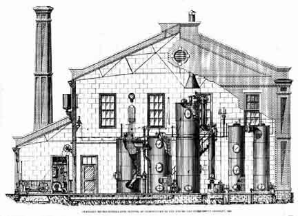
By the early 1900s, the standard brick manufactured gas plant had given way to a steel-framed brick-facade generator building of slightly taller nature, to accommodate the usual two-story layout of carburetted water gas. This plant, built on contract by the Stone & Webster Engineering Corporation (SWEC; Founded 1889, at Boston, Massachusetts, and owners, builders, and operators of many manufactured gas plants and yet in business as a subsidiary of The Shaw Companies), has the typical operator's floor above, with the bases of the generator set cylinders extending upward from the ground floor. The traditional monitor-style factor roof ridge is a preferred holdover from 19th century architectural tradition and promotes ventilation on hot days. A newer above-ground gas holder lies to the right rear and an obviously older gas holder is seen to the left, probably serving as the relief holder to buffer the pressure waves associated with moving from blow cycle to run cycle, every few minutes. (Photo from undated SWEC sales brochure of ca. 1925).
|
 |
|
U.G.I. 1890 Version Of T.S.C. Lowe's Carburetted Water Gas Plant T.S.C.
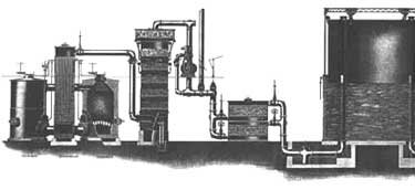
Lowe sold his basic carburetted water gas patents to the United Gas Improvement Company, of Philadelphia, in 1884, just two years after its founding. Lowe shortly moved west, to Pasadena, California, and became a leading civic, gas manufacturing personality, and developer of public attractions in Southern California. His base patents began to expire about 1892 and CWG units began to appear as marketed by other than U.G.I., notably the Gas Machinery Company (Cleveland), Bartlett-Hayward Company (Baltimore), Gas Engineering Co. (Trenton), Western Gas Construction Co. (Ft. Wayne, IN), Koppers Co. (Pittsburgh), and West Gas Improvement Co., of Britain. The term "water gas" was used loosely throughout the gas era, even in Brown's Directory of North American Gas Companies, and should be question-factored into site and waste characterization studies. This view, from an 1890 U.G.I. sales brochure portrays a single Generator Set of, from left to right, Generator, Carburetor, and Double Superheater, followed, on the right, by the Wash Box and two cylindrical Scrubber towers. Separated tar wastes were plumbed to transfer below the floor of this two story gas house. Note that there is a typical factory-type smoke stack at the boiler, with the blow-fume cylindrical chimney above the superheater shell.
|
|
|
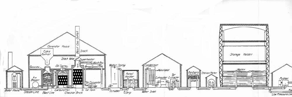
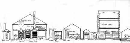
Combination Coal-Gas And Carburetted Water Gas Plant (ca. 1925)
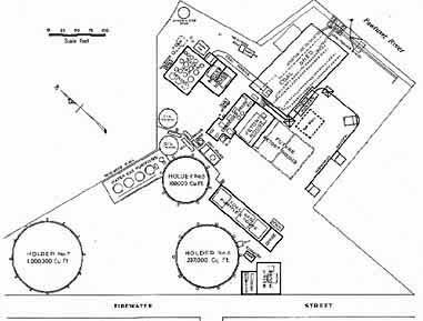
As noted above, an ideal combinational mix of gas manufacturing equipment was to generate gas and coke via coal-gas machines and to employ the coke for general plant heating of boilers and gas-making furnaces, then to employ the coke also as the reactor bed for the carburetted water gas generator sets. This design, by Stone & Webster, at Pawtucket, Rhode Island shows the related layout (Photo from an undated SWEC sales brochure of ca. 1925).
|
 |
|
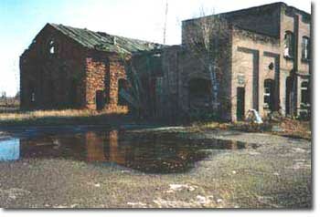
Hancock (Ripley), Michigan
Ruins of the FMGP at Hancock (Ripley), Michigan, a plant built for coal-gas generation and expanded to include carburetted water gas (CWG). There was a certain symbiosis in this dual operational capacity, in the years after widespread availability of CWG equipment (from the United Gas Improvement Company, of Philadelphia, purchasers of T.S.C. Lowe's patents in 1884) and before 1910, when coke produced at the coal-gas plant could be used to fire the plant boilers, to fire the furnace below the retort benches, and to serve as the feedstock-reactant bed of the CWG sets.
|
 |
|
Loomis Gas Producer (From Miller, 1910)
Gas Producers make up the forgotten bulk of American coal-tar sites. This technology produced "Blue" Water Gas, that is fuel gas made from coke or nearly any other organic matter, to thermally disassociate superheated steam into hydrogen gas (H2) and carbon monoxide (CO), both combustible at low Btu and without illumination qualities. The technology was suggested in Belgium in 1832 and pioneered in Britain in the 1850s by Sir William Siemens and perfected about 1861. Producer gas truly came into its own, in the U.S. about 1890 and continued in force until supplanted here and there by newly-arriving natural gas, mainly after 1930 and through 1960. Plants were installed in all manner of factories, in nearly every industry, especially those requiring heat. Factory owners bought the machines directly from manufacturers and operated them with plant personnel. Tars were generated and clarified and normally the waste waters and their tars were handled by options chosen by the factory management. There were hundreds of manufacturers across the nation. Patents were dodged in many ways, leading to the proliferation of designs. Shown is a Loomis Gas Producer, one of the leading varieties, as produced by the Loomis-Pettibone Company of New York City, NY.
"Bituminous coal contains a large amount of tarry vapors formed by the hydrocarbons, which condense on coming into contact with cold surfaces, and if these are drawn through an incandescent bed they add still further to the combustible ... If the tar cannot be so treated, it must be washed out of the gas together with the dust, water vapor, and the uncombined carbon dioxide." J.B. Rathbun, Consulting Gas Engineer, Chicago, IL, in Gas Engine Troubles and Installation, 1911.
|
|
|
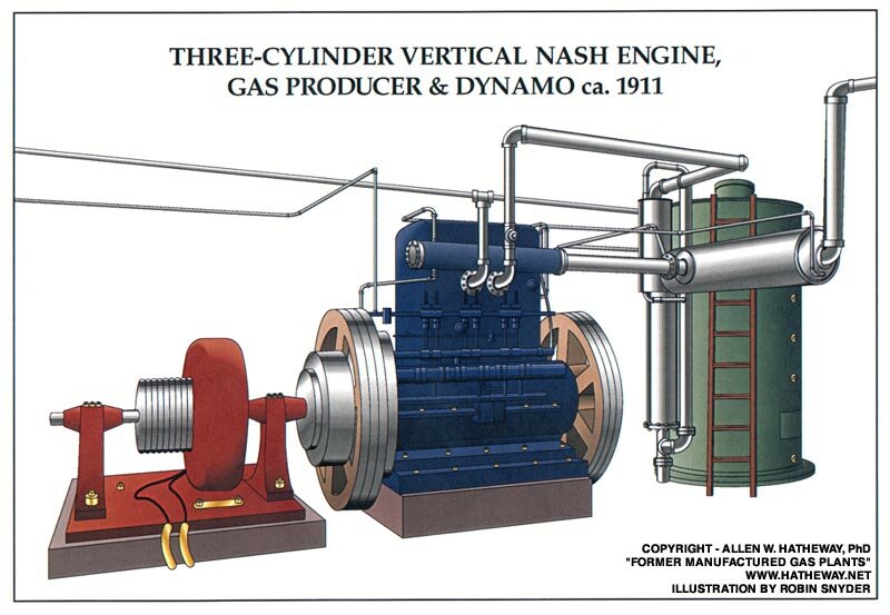
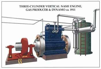
Producer Gas Engine
(Nash, Three-Cylinder Variety, ca. 1911)
Producer gas engines were the preferred power transfer medium for producer gas, here shown, in the center of the view (blue color), as driving an electric-generating D.C. dynamo (red color) and powered directly from the adjacent gas producer (green color). Normally, the entire gas producer set would be equipped with a condensing and washing tar removal device, with tar-bearing effluent sent through the floor and into some form of waste transport channel or sewer (Artwork by Ms. Robin Snyder, Gas Works Illustrator; [email protected]).
|
|
|
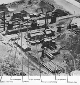
Coke Works, St. Louis, Missouri 1950
Low oblique aerial photograph of the Laclede Gas Light & Coke Company utility byproduct coke plant at Carondelet District of South St. Louis, Missouri. This configuration was the result of some modifications to the 1914 plant, built as an economic investment just prior to the start of World War I, in Europe. The entire site today measures about 16 ha. and lies at the juncture of the Mississippi River (top view) and the River des Peres, a major stormwater channel (shown to the right) of St. Louis. The site is geologically complex and contains karst features, an open tar pond, and an 1872-1905 coal-gas plant (not shown, but lying at the extreme west edge, beyond the lower edge of this view, along Broadway Blvd). The plant was abandoned by its third owner in 1987 and is the property of the St. Louis Community Redevelopment Authority and under a VCP order to its original builder. Historic activities that have gone on at this site include the first European settlement west of the Mississippi River (Tamaroa, 1700-1703; portions of riverboat Captain James B. Eads' Union Army gunboat works (1862-1865) , Carondelet Gas Light Company (1872-1905), the world-class Vulcan Steel Mill (1870-1888) and Balloon Training School V of the United States Army Signal Corps (1917-1918).
|
|
|
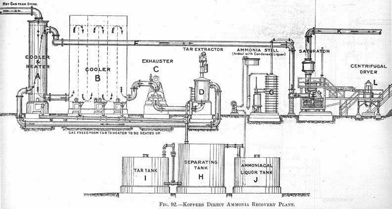
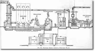
Koppers Direct Ammonia Recovery Plant (Post-1910)
Heinrich Koppers, a premier German gas engineer, emigrated to the United States in 1908 and enjoyed a brief but spectacular career in design of by-product coke ovens before his return to his native country in 1914, as a victim of the outbreak of the great European war. He sold his prosperous engineering company to Pittsburgh financiers headed by J.P. Morgan. The Koppers name became the leader in coke by-product plant design and much of the ongoing research in technologies for ever more efficient production of manufactured gas and of coal-tar by-products. The firm expanded into all aspects of the coal-tar chemical industry and provided the basis technology for production of synthetic rubber under the terrifying early days of World War II, with the loss of Asia to the Japanese. The Koppers firm eventually bankrupted under pressure of its numerous environmental remediation obligations. Shown is a late Koppers plant design for direct recovery of ammonia from a by-product coke-oven plant (click on the image for a larger version of this scanned image).
|
To Page #2 - TREATMENT COMPONENTS of the GAS PLANT
Copyright © 2018 by Dr. Allen W. Hatheway All rights reserved.
Individuals and organizations (Governmental, Corporate, Public Interest, Publishing Authors and The Media) wishing to make use of the contents, either for scholarly research, publication of any form, hardcopy or electronic, news media copy, and for various commercial purposes, such as website offerings of services, are herewith cautioned to make appropriate quotes of hatheway.net as the source of such materials, including the date upon which such materials were transferred to the above-stated personal or corporate use and to so inform Dr. Hatheway, electronically, as a courtesy. Professor Hatheway's offerings, constituting this website, are further subject to the Copyright & Legal Considerations appearing on the webpage by that name. For further information on Former Manufactured Gas Plants and related topics, please contact Dr. Hatheway at .
COPYRIGHT, IF YOU FIND THAT WE HAVE INADVERTENTLY VIOLATED COPYRIGHT ETIQUETTE, PLEASE LET US HAVE YOUR PROOF AND WE WILL GLADLY REMOVE THE OFFENDING ARTICLE.
|
 Visitors since 04/01/12 Visitors since 04/01/12
|
|